
Charge Air Cooling...
It is well documented that engines make more power when the inlet air is cooler. To understand what goes on during both the induction cycle and the power cycle when inlet air temperature is reduced, we need to consider both normally-aspirated and Supercharged petrol engines, We will also limit this discussion to four-cycle engines.
Before going any further, there are a couple of terms to define. For this article, it can be suggested that Supercharging is anything that increases the amount of oxygen available in the cylinder to support combustion of fuel above what could be expected from cylinder filling due to atmospheric pressure only. Take the assumption that atmospheric pressure at sea level to be 14.7 PSI and that “normal” air contains approximately 21 percent oxygen. Excluding oxygen-bearing fuels, such as Nitromethane, as a form of Supercharging, but inclusion of any form of mechanical compressor that pumps more air into an engine, such a belt- or gear-driven Supercharger, or an exhaust- or turbine-driven Turbocharger is included, as well as the injection of Nitrous oxide.
Airflow helps engines make power in a number of ways, but the truth is that the more air you can flow through an engine, the more oxygen mass that will be available for burning fuel at the correct fuel air ratio and that means more power. This is most evident when dealing with an ordinary normally-aspirated Petrol engine. Many performance methods relate to getting more air (read oxygen) into the cylinder. Whether it’s by installing a less restrictive throttle body or carburettor, a better flowing intake manifold, porting the cylinder head, larger valves, increasing camshaft lift or duration, the purpose is still the same – get more oxygen into the cylinders. The tuner is looking at getting maximum oxygen into the cylinder at wide open throttle for peak power. This is partly why Nitrous oxide (an oxygen-rich gas) injection is so effective. Nitrous oxide effectively increases the percentage of oxygen in the working fluid (which becomes a mixture of air, Nitrous oxide, and fuel) above the 21 percent oxygen in air alone. That means more fuel can be mixed into the working fluid also for greater combustion heat to expand the working fluid and increase pressure in the cylinder. Additionally, when the compressed Nitrous oxide, which is stored in its pressurized container as a liquid, is injected, it depressurizes and changes state from a liquid to gas, cooling the working fluid for an accompanying density increase. Of course, it would take an incredible amount of nitrous oxide to be able to achieve this at all times, so as you would expect, nitrous oxide injection is only used on demand at wide open throttle. But what if we could get more oxygen into the engine at all throttle positions all the time?
The air throttle body on a Petrol engine controls the density of the intake charge that enters the cylinder. It is also explained how Superchargers and Turbochargers increase the density under boost conditions. In some regards, it can be viewed as density as the amount of oxygen crammed into a given volume of air (the working fluid). Increased density means the molecules in the air are closer together in the same space – more air mass (and oxygen) in the same space. However, there has to be consideration for increased air density in both unconfined and confined spaces. Looking at an unconfined space, such as the atmosphere, because that is what is available to the normally-aspirated engine. Two things affect air density in the atmosphere – pressure and temperature. As atmospheric pressure goes up, indicated by higher barometric pressure on a barometer, the density increases if the temperature stays the same. In other words, at any given temperature, if the barometric pressure rises, so does the air density. By the same token, as temperature goes down, the density increases if the atmospheric pressure stays the same. Atmospheric air density is very important to normally aspirated engines. Obviously, there is not much that can be done to increase the atmospheric air pressure in regard to a normally-aspirated engine, it could potentially be enhanced slightly with some form of Ram air taken either from the front of the vehicle or from a dynamically high pressure area, assuming that the vehicle is travelling at sufficient speed to enable a dynamic pressure rise. More importantly, in most cases you can do something about the temperature of the inlet air. The object is to get the coolest air possible to the engine’s intake system. Some engines can induct air that has passed through the radiator or over other warm areas of the engine, significantly heating the air and reducing its density.
Ensuring the air intakes/ ducts/ filters source air that hasn’t been warmed by the engine bay, density is significantly increased by comparison to the engine inducting hotter air. For example, it is not uncommon for air to increase up to 40 degrees above atmospheric ambient inside the engine bay having passed through the radiator, air conditioning condenser and other heat exchangers on vehicles, then factor in exhaust manifolds and this problem is further exacerbated. This less dense air can have effects on the weight of air mass through the compressor and potentially change compressor performance in relation to the compressor map.
If cooler, or higher density air is available at all throttle positions, it means that the engine is capable of producing given amounts of power at lesser throttle openings. This generally equates to better fuel economy. It also means the engine has greater power potential for accelerating or climbing gradients. Cooler intake air also aids in the suppression of detonation since the Cylinder charge air doesn’t reach as high peak temperature on the compression stroke – again, a plus for accelerating or climbing with the engine under high load. Superchargers and Turbochargers significantly heat the intake air as they compress it to create boost, depending on the compressor efficiency and the pressure ratios that the compressor is being expected to deliver. The higher boost pressure increases the air density, but large increases of temperature of the air from low efficiency compressors can largely offset and even negate this density gain. In this case, it is relating to the effects of pressure and temperature in a confined space, the intake system. Consequently, it is desirable to cool the compressed air before it enters the engine. In most cases, especially where boost levels exceed 7 PSI, cooling the compressed air with a Charge air cooler, often called an intercooler, increases the air density more than any density losses that occur due to the accompanying pressure drop due to cooling or flow restrictions through an intercooler. In other words, intercooling/chargecooling results in a net density increase for the air entering the cylinder.

Intercooling/Chargecooling can also potentially provide other benefits. For Supercharged or Turbocharged petrol engines, reducing the intake air temperature not only aids the suppression of detonation, it can also result in lower peak cylinder temperatures which can reduce emissions, and lower peak exhaust gas temperatures which can aid in the survival of exhaust valves where a few degrees can make all the difference. It has been shown that any reduction in inlet air temperature is then reflected into that of exhaust gas temperature.
Intercooler cores can be of either Tube and Fin or Bar and Plate horizontal flow design. Tube and Fin are stacks of extruded tubes sandwiched between the fin layers, Bar and Plate are Vacuum brazed components that go to make up the passages for the air to pass, Both types have their Pros and Cons. Charge air from the Supercharger flows within enclosed passages in one direction, with separate cooling passages flowing cooler ambient air in a 90 degree perpendicular flow pattern to the charge air. In bar and plate designs the passages consist of plates on top and bottom with fins in between. The passages are enclosed by bars on either side depending on if it is a charge air passage or an ambient air/cooling passage. Passages are stacked alternately until the desired stack height is reached. On the sides of the stacked cores, added to the final passage is a side plate of thicker material to provide structural integrity, protect the more delicate fins, and provide a surface for welding on end tanks if desired. With Tube and Fin, the tubes are of a pre sized extruded dimension of core thickness and generally around 7- 8mm in height with the turbulators internally part of the extrusion. With both types Fin height, fins per inch, number of tubes/charge air passages core size and orientation effect the Intercoolers performance/efficiency.
Fin density is measured in FPI or fins per inch. Each fin surface counts as one fin meaning there are two fins per wave. Fin stacks start off as flat sheets of Aluminium that are fed through a special machine where they are bent to the desired FPI per row height and length. Each core can be different in length, width, and height to satisfy the needs of different performance engines.
Intercooler cores utilize a combination of fin density depending on the flow path of the core. For example, the cold flow path or the front of the intercooler usually has a higher density fin count to allow for better thermal performance and cooling. Core width/ cold flow can range from 50mm – 125mm so a higher fin density is critical with the short span the ambient air has to flow across to cool the charge air passages. Additionally, the cold air passages are not sealed or pressurized like the charge air passages, so your ambient air flows through, cools the hot passages and evacuates into the engine compartment.
Hot flow passages have a longer run spanning from 200mm-600mm in some Intercooler cores. The hot flow path is a series of sealed chambers with fins spanning the entire length. There is a lot of surface area for heat transfer to take place, and for that reason, the hot chambers have a lower fin density. This also helps reduce pressure drop as the charge air travels from one side to the other.
The intercooler removes heat from the charge air by types of heat transfer, the Intercooler relies on Conduction and Convection to extract heat from the charge air. Conduction is the transfer of heat to materials that have direct contact with each other. Convection is the transfer of heat from one place to another by movement of air. This is the reason that turbulator and fin density is important, air contact surface area to exchange heat. The charge air turbulator fins transfer heat from the charge air to the plates/tubes and the ambient air fins transfer the heat from the plates/tubes due to the ambient airflow cooling those fins. The process repeats as long the vehicle is moving or until the core gets heat soaked, which is why Intercooler size and location is important.
Intercooler Cores that have thinner depth section but greater surface area of frontal matrix exposed to the ambient cooling airflow passing through them generally perform better than cores that are smaller in frontal area but have a greater depth. This is due to the fact that as the ambient air passing through a deeper core is increasing in its temperature and slowing in velocity as it passes through the core reducing its efficiency.
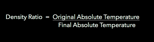
Intercooler efficiency as a heat exchanger, its ability to cool the compressor charge air passing through it, is reflected by the atmospheric ambient air temp as the cooling medium and the Intercooler design/area. The Density ratio, ie the change in density through the Intercooler/Chargecooler is defined as;
Pressure drop is the difference in pressure between two points caused by flow resistance. An example of pressure drop is when the air pressure leaving the Intercooler outlet is less than the pressure at the inlet. All Intercooler/Chargecoolers will present some form of pressure drop depending upon the Boost level/flow, number of passages available for charge air flow (area) and the internal turbulator fin design, typically the value is 0.1-2psi depending on designs and pressures.
Air to Water Charge air coolers are doing the same task as the Air to Air Intercooler, to remove heat from the Compressor charge air and increase its density. The construction of an Air to Water Chargecooler is essentially the same as per the Air to Air. The difference is that, now it is not ambient air flowing over the external passage ways but water held around the core with an Aluminium jacket. The water in the system is circulated via header tank, pipe work and electric pump into a ‘conventional radiator’ heat exchanger to cool the water that has taken heat from the Compressor charge air matrix. Water can remove a lot of heat energy as a medium, but there can be inefficiencies in the system due to having to transfer heat into the water and then using another heat exchanger to remove that heat from the water with ambient temperature airflow. Factor in to this that if the vehicle is not moving then the water heat exchanger cannot remove heat from the system and as with an Air to Air Intercooler Heat soak can be a problem. This type of Chargecooler becomes very effective if employing a header tank that is Ice filled and has Super cooled water circulating which can bring Chargecooler matrix temperatures well below ambient therefore significantly increasing its cooling efficiency, obviously with long duration use the water eventually heats up and negates the benefits.
Whilst on the subject of water, it is worth considering Water/Methanol injection. As mentioned water can remove a substantial amount of heat energy, Latent heat evaporation. With Water/Methanol injection the amount energy to change the water state requires a lot of energy (heat) to do. By mixing Flammable Methanol at a ratio of 50/50 which is water soluble, prevents the water freezing and evaporates even more readily creates a very potent method of removing heat from the charge air and adds a percentage of fuel via the Methanol. This does not add instantaneous power, however it can add an effective Octane increase, it can allow higher Boost pressures, it can allow further ignition advance, it does aid the cleanliness of the combustion chamber, it can significantly reduce peak cylinder temperatures and allow potential tuning that other cooling methods would not be able to match. Consideration must be given to the pump pressure, usually 160-200psi, supply lines, nozzle sizes in relation to airflow/Hp, nozzle locations, supply tank location/volume and how the system is operated/controlled, ie with Boost pressures or with electronic methods and the employment of solenoids and sensors and of course fail safes.